LoRa Sender and Receiver with Dormant and RTC Alarm (RP2040)
Bill of Materials
| Item | Quantity | Description | Notes |
|---|---|---|---|
| Raspberry Pi Pico | 2 | Microcontroller Board | Main controller |
| LoRa SX1278 Module (LoRa 433MHz Ra-02) | 2 | LoRa Module | for remote communication |
| 433 MHz Antenna | 2 | Antenna with IPEX Socket | for LoRa Module |
| Jumper Wires | 8 | Male-to-Female cables | For connections |
| Jumper Wires | 17 | Female-to-Female cables | For connections |
| LED (Red) | 2 | 5mm LEDs | For indicators |
| LED (Green) | 2 | 5mm LEDs | For indicators |
| Resistor (1kΩ) | 2 | Current limiting | For LEDs |
| Resistor (470Ω) | 2 | Current limiting | For RED LEDs |
| Breadboard | 2 | Prototyping board | For wiring |
General explanation
The first part of this project focuses on the main functionality of the "Presence Light". It consists of a sender and receiver device, which communicate via an encrypted LoRa messaging. Since these devices will be battery powered, the most important part is to be as efficient as possible. Usually that can be done by putting the microcontroller into a "sleep mode". In my case there won´t be a frequent use, but the devices have to be powered the whole time, which would empty the batteries really fast.
Luckily most ARM microcontrollers I know, have some special state where they are almost turned off to save power, this state is mostly called DEEPSLEEP or DORMANT. I don´t have a high precision current measurement device, but the current monitor on my HANMATEK HM310 power supply shows a current of 0.000 A, when my RP2040 is in DORMANT mode.
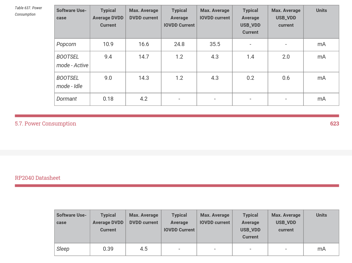
Figure 1 shows that the Raspberry Pi Pico (RP2040) in the "BOOTSEL mode - Active", according to the manual, draws an average current of
9.4 mA + 1.2 mA + 1.4 mA = 12 mAThis mode would be the closest to the startup or initial mode(This doesn´t include devices like the LoRa SX1278 Module which draw around 12-18 mA in IDLE mode). Just for simplicity, if we compare the average current consumption between "BOOTSEL mode - Active" without any other devices and the DORMANT mode
12 mA ÷ 0.39 mA = 30.76we get a 30 times higher current consumption in "BOOTSEL mode - Active" than in DORMANT. That would be detrimental on a longer time period.
If we had a battery which can provide 1000 mAh in "BOOTSEL mode - Active"
t = 1000 mAh ÷ 12 mA = 83.3 h = 3.472 d
the battery would be emptied on the fourth day. In DORMANT Mode + WAKEUP Phases, lets say an average current of 1 mA = 1000 h = 41.6 d
As i said this difference gets even bigger when there is a LoRa device powered by the RP2040, because in DORMANT mode the internal 3V3 power supply of the PI turns off, which suplies the voltage for the SX1278 in my case.
You see, that this is a big reason for me and other developers to use these DEEPSLEEP or DORMANT modes to save power, especially when there is only a limited amount of it available.
Structure
Since I have a sender and a receiver, I have to put both devices in a
DORMANT/DEEPSLEEP mode. The sender will react to a RISING edge on two
different pins, LED-Present(Green) and LED-Not-Present(RED).
The receiver will be woken up every second by an RTC alarm, to check if
there is a LoRa signal available. The reason I have decided to do it
like this, was because the receiver needs some kind of interrupt to wake
up but will not have the user "push a button" to put a "HIGH" signal on
some GPIO port. The LoRa device has a CAD (Channel Activity
Detection)-mode, but will not induce a HIGH Signal on the DIOn (DIOn
Interrupt) pins just by sensing a signal (I thought it was like that
before), even when powered separately(so it doesn´t turn off when the
RP2040 is in DORMANT). It needs the SPI bus to be active to show this
reaction.
So the process will be like this:
- User pushes a button -> puts a HIGH signal on one of the configured GPIO ports to trigger a GPIO-Interrupt on the sender device.
- Sender wakes up (including clocks and PLL´s) activates the SPI bus and sends an encrypted message for around 1.1 seconds. With the receiver waking up every second it is guaranteed that the receiver will get the message since the sender sends a little longer than the wake up period of the receiver is configured.
- The receiver wakes up every second and senses the signal, if available. Then gets the encrypted message, decrypts it and if the message is correct, it activates one of the LED´s.
- Receiver sends some kind of "Acknowledged"-message multiple times and goes for another second into DORMANT mode.
- The sender receives the message and then turns on one of the LED´s. After that, the sender device goes into DORMANT mode again until another button is pushed.
Of course there is a constant current consumption of the LED´s. That is why I want to use the E-Ink displays in the next part/sub-project. (So stay excited for the next sub-project 😉)
This is my simple structure to realize this part of the bigger project. But for now we´ve talked enough about theory, so lets start building and programming.
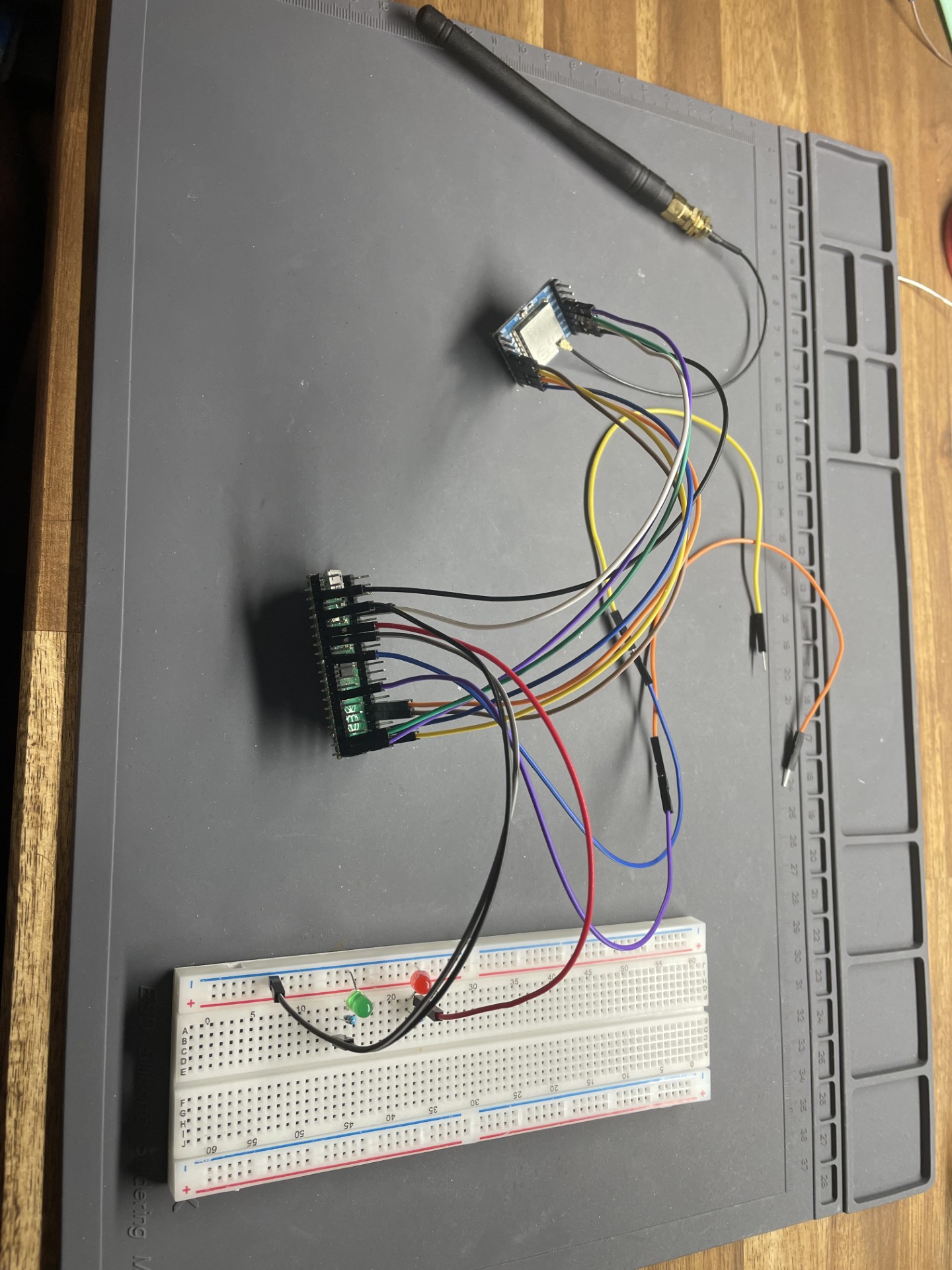
Hardware
As mentioned before, the hardware of the sender, as well as the receiver consist of the Raspberry Pi Pico and the SX1278 Module. The difference is only done by the firmware and some connections. The following table shows the connections between each RP2040 and the LoRa Modules.
| Function | SX1278 Pin | RP2040 (Sender/Receiver) |
|---|---|---|
| VCC | VCC | 3V3 |
| GND | GND | GND |
| MISO | MISO | GP16 |
| MOSI | MOSI | GP19 |
| SCK | SCK | GP18 |
| NSS (Chip Select) | NSS | GP17 |
| RESET | RST | GP14 |
| DIO0 (Interrupt) | DIO0 | GP15 |
Additionally for the sender the following Pins are used:
| Function | RP2040 Sender |
|---|---|
| Interrupt for "is present" | GP10 |
| Interrupt for "is not present" | GP7 |
| Green LED (is present) | GP3 |
| Red LED (is not present) | GP5 |
| GND for the LED´s | GND |
The receiver uses following three Pins to drive the LED´s:
| Function | RP2040 Receiver |
|---|---|
| Green LED (is present) | GP6 |
| Red LED (is not present) | GP9 |
| GND for the LED´s | GND |
Please when connecting the LED´s on the Breadboard connect the resistors in series to the LED´s, 470 Ω for the red ones and 1 kΩ for the green ones, in both cases!
Firmware
The firmware is written in the Arduino IDE. There are functions on the SLEEP and DORMANT modes in the pico-extras library on github
https://github.com/raspberrypi/pico-extras, but for the sake of understanding it better I didn´t realy want to use them. Also, i have read on many websites that people who used this library, have had problems with the wake up or it was hanging. So i wanted to invest the time to read through the manual and try it out myself.
Sender
First we need to understand how we have to operate with the RP2040. The question is: "How to go into DORMANT mode?"
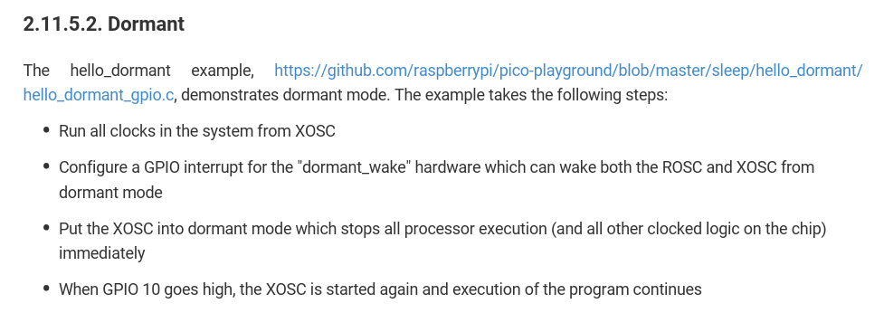
The screenshot of the manual on Figure 4 tells us to operate in following order:
- Run all clocks from the on board crystal(XOSC) which has a frequncy of 12 MHz (RP2040). This will make it possible to stop all the other clocks and pll´s.
- Configure 2(in our case) GPIO-Interrupts, which will make the RP2040 wake up.
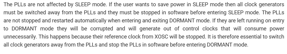
- Stop the 2 pll´s, meaning system pll and usb pll, because shortly they would draw current in DORMANT mode (perfectly written in the manual - see figure 5).
- Lastly, put the ONLY running clock source, the XOSC, into DORMANT mode to stop the processor.
When in our case GP10 or GP7 goes HIGH, the processor wakes up, so we need to reconfigure the clocks, send the message and do the same schedule again.
In the github library they use a function which they also have in the manual on page 163:
void sleep_goto_dormant_until_pin(uint gpio_pin, bool edge, bool high) {
    bool low = !high;
    bool level = !edge;

    // Configure the appropriate IRQ at IO bank 0
    assert(gpio_pin < NUM_BANK0_GPIOS);

    uint32_t event = 0;

    if (level && low) event = IO_BANK0_DORMANT_WAKE_INTE0_GPIO0_LEVEL_LOW_BITS;
    if (level && high) event = IO_BANK0_DORMANT_WAKE_INTE0_GPIO0_LEVEL_HIGH_BITS;
    if (edge && high) event = IO_BANK0_DORMANT_WAKE_INTE0_GPIO0_EDGE_HIGH_BITS;
    if (edge && low) event = IO_BANK0_DORMANT_WAKE_INTE0_GPIO0_EDGE_LOW_BITS;

    gpio_init(gpio_pin);
    gpio_set_input_enabled(gpio_pin, true);
    gpio_set_dormant_irq_enabled(gpio_pin, event, true);

    _go_dormant();
    // Execution stops here until woken up

    // Clear the irq so we can go back to dormant mode again if we want
    gpio_acknowledge_irq(gpio_pin, event);
    gpio_set_input_enabled(gpio_pin, false);
}
Essentially this function configures a GPIO interrupt and goes into DORMANT Mode.
Don´t worry, I will explain it thoroughly, but for that I will go through the steps with my code and explain the functions in detail,
Go to Dormant with both GPIO Interrupts configured on RISING EDGE
// Configure GPIO-Interrupt for DORMANT Wake-Up
void  sleep_goto_dormant_until_pin(uint gpio_pin1, uint gpio_pin2, bool edge, bool high) {

    bool low = !high;
    bool level = !edge;

    // Configure the appropriate IRQ at IO bank 0
    assert(gpio_pin1 < NUM_BANK0_GPIOS);
    assert(gpio_pin2 < NUM_BANK0_GPIOS);

    uint32_t event = 0;

    if (level && low) event = IO_BANK0_DORMANT_WAKE_INTE0_GPIO0_LEVEL_LOW_BITS;
    if (level && high) event = IO_BANK0_DORMANT_WAKE_INTE0_GPIO0_LEVEL_HIGH_BITS;
    if (edge && high) event = IO_BANK0_DORMANT_WAKE_INTE0_GPIO0_EDGE_HIGH_BITS;
    if (edge && low) event = IO_BANK0_DORMANT_WAKE_INTE0_GPIO0_EDGE_LOW_BITS;

    gpio_set_dormant_irq_enabled(gpio_pin1, event, true);
    gpio_set_dormant_irq_enabled(gpio_pin2, event, true);

    // Execution stops here until woken up
    enter_dormant_mode();

    wake_up_from_dormant();

    // Clear the irq so we can go back to dormant mode again
    gpio_acknowledge_irq(gpio_pin1, event);
    gpio_acknowledge_irq(gpio_pin2, event);
}
Of course I have copied what is already written in the lib. I just
changed it to configure 2 GPIO Interrupts. The
uint gpio_pin1 and uint gpio_pin2 are the pins
used. Then there are the variables bool edge and
bool high .
Now lets break the function down. Lets say we want the interrupts to
fire on a rising EDGE. We would pass edge = true and
high = true into this function. The variables
low and level will be false.
After that the assert() function checks if the input GPIO
exists, if not it returns an error and stops the function here. But
since we input an existing GPIO (7 and 10), it will just go through.
Then, it simply configures the event on which my interrupts will fire.
In our case the third condition is selected.
event = IO_BANK0_DORMANT_WAKE_INTE0_GPIO0_EDGE_HIGH_BITS
means "fire on rising edge".
The chosen event gets passed with each GPIO-pin into
gpio_set_dormant_irq_enabled. Now both interrupts are
configured. Next, the device will enter dormant with the function
    // Execution stops here until woken up
    enter_dormant_mode();
Immediately after the wake up, the function
wake_up_from_dormant();
is called to reconfigure the clocks and pll´s.
Lastly the IRQ´s are cleared to be able to go to DORMANT again.
Let´s start entering the DORMANT mode
void enter_dormant_mode() {

//The crystal initialized
xosc_init();

switchAllClocksToXOSC();

rosc_disable();

disable_all_plls();

xosc_dormant();

uint save = scb_hw->scr;
// Enable deep sleep at the proc
scb_hw->scr = save | M0PLUS_SCR_SLEEPDEEP_BITS;

// wait for interrupt - the processor goes into standy/sleep - code stops here
__wfi();

//Reconfigure the registers to the original
scb_hw->scr = save;

}
The xosc_init() starts and initializes the crystal,
remember thats what we wanted to do. The function
switchAllClocksToXOSC() makes the clk_ref get
it´s clock from the XOSC.
The clk_ref is the reference clock, which initially runs
from the ROSC (manual p. 169). So the reference clock is now sourced by
the XOSC and not the ROSC anymore and also outputs the same frequency(12
MHz), as configured. The system clock(pll_sys) runs on
power up from clk_ref but switches to pll_sys.
We want it to get sourced by the reference clock. Now the reference and
system clock operate both on 12 MHz. We have "decoupled" the main clocks
from the pll´s. All the other clocks are stopped because they are not
needed at this point. Notice the serial monitor will stop because the
clk_usb stops.
void switchAllClocksToXOSC() {

  clock_configure(clk_ref, CLOCKS_CLK_REF_CTRL_SRC_VALUE_XOSC_CLKSRC, 0, 12 * MHZ, 12 * MHZ);
  //set clk_sys to get its clock from reference clock which gets its clock from xosc
  clock_configure(clk_sys, CLOCKS_CLK_SYS_CTRL_SRC_VALUE_CLK_REF, 0, 12 * MHZ, 12 * MHZ);

  //stop all other clocks
  clock_stop(clk_peri);
  clock_stop(clk_usb);
  clock_stop(clk_adc);
  clock_stop(clk_rtc);

  clock_stop(clk_gpout0);
  clock_stop(clk_gpout1);
  clock_stop(clk_gpout2);
  clock_stop(clk_gpout3);

}
Now that no clock is sourced by ROSC or any of the two pll´s, all can be stopped.
void rosc_disable() {
  uint32_t tmp = rosc_hw->ctrl;
  tmp &= (~ROSC_CTRL_ENABLE_BITS);
  tmp |= (ROSC_CTRL_ENABLE_VALUE_DISABLE << ROSC_CTRL_ENABLE_LSB);

  rosc_hw->ctrl = tmp;
  // Wait for it to stabilize
  while(rosc_hw->status & ROSC_STATUS_STABLE_BITS);
}
// Deactivate both pll´s of rp2040
void disable_all_plls() {
  pll_deinit(pll_usb);
  pll_deinit(pll_sys);
}
xosc_dormant()
is provided by the lib and sets the register of the XOSC to go into
dormant.
We save the SCB(System Control Block) of the ARM Cortex M0+ before
setting the SLEEPDEEP bits, call __wfi() to put the
processor in a sleep state. After the wakeup we go back to the saved SCB
configuration.
That´s it for the DORMANT part. The only thing left is the reconfiguration after wake up.
Reconfiguration after Wakeup
void wake_up_from_dormant() {

  //ENABLE ROSC again
  rosc_hw->ctrl = (rosc_hw->ctrl & 0xFF000FFF) | (ROSC_CTRL_ENABLE_VALUE_ENABLE << 12);
  while(rosc_hw->status & ROSC_STATUS_STABLE_BITS);

  restart_all_plls();

  reconfigureAllClocksAfterWakeUp();
}
We enable the ROSC, the XOSC gets enabled through
gpio_set_dormant_irq_enabled(when it was set to dormant
before), so no need to do that. After that the pll´s are activated:
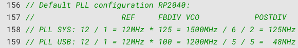
void restart_all_plls() {

  //Configuration of the system PLL with 125 MHz as target
  pll_init(pll_sys, 1, 1500 * MHZ, 6, 2);

  //reinitializing the USB-PLL to 48 MHz
  pll_init(pll_usb, 1, 480 * MHZ, 5, 2);

}
The calculation of the pll frequency can be seen in figure 6.
Lastly the clocks are reconfigured to the desired frequency. Which
frequency to choose is written on page 183 in the manual, for example
the clk_rtc should be 46875 Hz. The pll´s are used again.
void reconfigureAllClocksAfterWakeUp() {

  //sys will get its clock from sys pll which is configured to 125 MHz
  clock_configure(clk_sys, CLOCKS_CLK_SYS_CTRL_SRC_VALUE_CLKSRC_CLK_SYS_AUX, CLOCKS_CLK_SYS_CTRL_AUXSRC_VALUE_CLKSRC_PLL_SYS, 125 * MHZ, 125 * MHZ);
  //sys pll -> clk_peri 125 MHz
  clock_configure(clk_peri, 0, CLOCKS_CLK_PERI_CTRL_AUXSRC_VALUE_CLK_SYS, 125 * MHZ, 125 * MHZ);
  //usb pll -> clk_usb 48 MHz
  clock_configure(clk_usb, 0,CLOCKS_CLK_USB_CTRL_AUXSRC_VALUE_CLKSRC_PLL_USB, 48 * MHZ, 48 * MHZ);
  //usb pll -> clk_adc since it also needs 48 MHz
  clock_configure(clk_adc,0, CLOCKS_CLK_ADC_CTRL_AUXSRC_VALUE_CLKSRC_PLL_USB,  48 * MHZ, 48 * MHZ);
  //xosc -> clk_rtc 46875 Hz
  clock_configure(clk_rtc, 0, CLOCKS_CLK_RTC_CTRL_AUXSRC_VALUE_XOSC_CLKSRC,  12 * MHZ, 46875);
}
Alltogether the whole loop process looks like this
#include <SPI.h>
#include <SPI.h>
#include <AES.h>
#include "hardware/xosc.h"
#include "hardware/pll.h"

//simple key for encrypting a message
uint8_t key[32] = {
    0x1A, 0x10, 0xC4, 0xD5, 0xE6, 0x7F, 0x8A, 0x9B,
    0x0C, 0x1D, 0x2E, 0x3F, 0x4A, 0x5B, 0x6C, 0x7D,
    0x8E, 0x9F, 0xAA, 0x2B, 0xC7, 0xCA, 0xFE, 0x2F,
    0x12, 0x24, 0x33, 0x10, 0x44, 0x66, 0x77, 0x58
};

AES256 aes;


static uint8_t wake_up_pin = 0;


#define WAKEUP_PIN_ON 10
#define WAKEUP_PIN_OFF 7

#define PIN_RECEIVER_LED_ON 3
#define PIN_RECEIVER_LED_OFF 5

// Pins for sx1278 lora module to rp2040
#define SS 17    // Chip Select Pin
#define RST 14   // Reset Pin
#define DIO0 15  // IRQ Pin

uint8_t encrypted[16];
uint8_t decryptedResponse[16];
uint8_t sendTextOn[16] = "LED ON";
uint8_t sendTextOff[16] = "LED OFF";


bool checkForResponse(){
  int packetSize = LoRa.parsePacket();
  if (packetSize) {

    //read received string
    while (LoRa.available()) {
      String received = LoRa.readString();

      uint8_t* receivedBytes = stringToBytes(received);
      aes.decryptBlock(decryptedResponse,receivedBytes);

      if(checkReceivedTextCorrect(decryptedResponse,"LED ON OK")) {
        digitalWrite(PIN_RECEIVER_LED_ON, HIGH);
        digitalWrite(PIN_RECEIVER_LED_OFF, LOW);

        return true;
      }
      else if(checkReceivedTextCorrect(decryptedResponse,"LED OFF OK")) {
        digitalWrite(PIN_RECEIVER_LED_OFF, HIGH);
        digitalWrite(PIN_RECEIVER_LED_ON, LOW);

        return true;
      }

    }
  }
  return false;
}

bool checkReceivedTextCorrect(uint8_t* decryptedText, String textToCompare){
  uint8_t counter = 0;
  for(int i=0; i < textToCompare.length(); i++) {
    if(textToCompare[i] == (char)decryptedText[i]) counter++;
  }
  return counter == textToCompare.length() ? true:false;
}

void setup() {

  //Delay for flashing so it doesnt go dormant during flashing
  delay(5000);

  // GPIO 10 as input for the wake up
  gpio_init(WAKEUP_PIN_ON);
  gpio_set_dir(WAKEUP_PIN_ON, GPIO_IN);
  gpio_pull_down(WAKEUP_PIN_ON); // Internal pullup for the pin

  gpio_init(WAKEUP_PIN_OFF);
  gpio_set_dir(WAKEUP_PIN_OFF, GPIO_IN);
  gpio_pull_down(WAKEUP_PIN_OFF); // Internal pullup for the pin


  // Interrupt für beide Pins aktivieren
  gpio_set_irq_enabled_with_callback(WAKEUP_PIN_ON, GPIO_IRQ_EDGE_RISE, true, &gpio_callback);
  gpio_set_irq_enabled_with_callback(WAKEUP_PIN_OFF, GPIO_IRQ_EDGE_RISE, true, &gpio_callback);


  //on board led for debugging
  pinMode(LED_BUILTIN, OUTPUT);

  pinMode(PIN_RECEIVER_LED_ON, OUTPUT);
  pinMode(PIN_RECEIVER_LED_OFF, OUTPUT);

  // Set the LoRa-Pins
  LoRa.setPins(SS, RST, DIO0);

  // initialize LoRa with 433 MHz (frequency of SX1278)
  if (!LoRa.begin(433E6)) {
    while (1);
  }
  LoRa.enableCrc();

  //simple encryption for sender - receiver pair
  aes.setKey(key, sizeof(key));

}


void loop() {
  bool messageSent=false;
  uint8_t i = 0;

  //Wait for fifo to end
  uart_default_tx_wait_blocking();

  //sleep until rising edge
  sleep_goto_dormant_until_pin(WAKEUP_PIN_ON, WAKEUP_PIN_OFF,true, true);


  // -------------------------------------------------------------------------------------------------------- //
  // ---------------------------- sending package depending on wakeup pin ----------------------------------- //
  // -------------------------------------------------------------------------------------------------------- //

  //sends 18 times in row to send the whole wakeup time (1second) of receiver (1.1seconds)
  if(wake_up_pin == WAKEUP_PIN_ON){

    while(i<18){
      aes.encryptBlock(encrypted,sendTextOn);

      LoRa.beginPacket();
      LoRa.print(bytesToString(encrypted));
      LoRa.endPacket();

      delay(60);
      i++;
    }
    messageSent = true;
  }
  else if(wake_up_pin == WAKEUP_PIN_OFF){

    while(i<18){
      aes.encryptBlock(encrypted,sendTextOff);

      LoRa.beginPacket();
      LoRa.print(bytesToString(encrypted));
      LoRa.endPacket();

      delay(60);
      i++;
    }
    messageSent = true;
  }

  wake_up_pin = 0;


  // ------------------------------------------------------------------------------------------------------- //
  // ------------------------------ wait for response of the receiver -------------------------------------- //
  // ------------------------------------------------------------------------------------------------------- //

  if(messageSent == true){
    messageSent = false;

    //wait for response for 1.5 seconds
    unsigned long startTime = millis();
    while(millis() - startTime < 1500){


      int packetSize = LoRa.parsePacket();
      if (packetSize) {

        //read received string
        while (LoRa.available()) {
          String received = LoRa.readString();

          uint8_t* receivedBytes = stringToBytes(received);
          aes.decryptBlock(decryptedResponse,receivedBytes);

          if(checkReceivedTextCorrect(decryptedResponse,"LED ON OK")) {
            digitalWrite(PIN_RECEIVER_LED_ON, HIGH);
            digitalWrite(PIN_RECEIVER_LED_OFF, LOW);
          }
          else if(checkReceivedTextCorrect(decryptedResponse,"LED OFF OK")) {
            digitalWrite(PIN_RECEIVER_LED_OFF, HIGH);
            digitalWrite(PIN_RECEIVER_LED_ON, LOW);

          }

        }
      }

      delay(80);
    }
  }
}
The structure I have shown on figure 2 is now implemented in the code.
Simply put: wake up by interrupt -> reconfigure clocks -> encrypt message -> send for 1.1 seconds -> wait for response for 1.5 seconds -> if response comes turn on LED
Receiver
After explaining the structure and functions in the sender section, we can go faster through the receiver code. The main difference is waking up by an rtc alarm instead of a GPIO-Interrupt.
// Months with their maximum days (non-leap year)
const int days_in_month[] = { 31, 28, 31, 30, 31, 30, 31, 31, 30, 31, 30, 31 };

//wrong time but doesn´t matter
datetime_t t = {
      .year  = 2025,
      .month = 2,
      .day   = 8,
      .dotw  = 6,  // 0 = sunday, 1 = monday, ..., 6 = saturday
      .hour  = 10,
      .min   = 26,
      .sec   = 0
};

void setup() {


  rtc_init();
  delay(10);

  //set rtc time once
  rtc_set_datetime(&t);

  pinMode(LED_BUILTIN, OUTPUT);
  pinMode(GPIO_LED_ON, OUTPUT);
  pinMode(GPIO_LED_OFF, OUTPUT);


  delay(5000);


  // initialize LoRa-Module
  LoRa.setPins(SS_PIN, RST_PIN, DIO0_PIN);

  if (!LoRa.begin(433E6)) {
    while (1);
  }

  LoRa.enableCrc();
  aes.setKey(key, sizeof(key));

}

void loop() {

  uart_default_tx_wait_blocking();
  // sleep for a second
  enter_dormant_mode_with_timer(1);


  int packetSize = LoRa.parsePacket();
  if (packetSize) {

    // Read and display received data
    while (LoRa.available()) {
      String received = LoRa.readString();

      uint8_t* receivedBytes = stringToBytes(received);

      //Decrypt
      aes.decryptBlock(decrypted,receivedBytes);

      if(checkReceivedTextCorrect(decrypted,"LED ON")) {
        digitalWrite(GPIO_LED_ON, HIGH);
        digitalWrite(GPIO_LED_OFF, LOW);

        //Success send response
        sendResponse(sendTextOn);

      }
      else if(checkReceivedTextCorrect(decrypted,"LED OFF")) {
        digitalWrite(GPIO_LED_OFF, HIGH);
        digitalWrite(GPIO_LED_ON, LOW);

        //Success send response
        sendResponse(sendTextOff);

      }


    }

  }

}
Starting with the setup() we immediately initialize the rtc
and set the datetime. the variable t needs to be of the
type datetime_t , it doesn´t matter in our case to have the
correct time, because we wont display the time or use it that specific.
We only want the RP2040 to wake up every second.
The function enter_dormant_mode_with_timer(1) in the
loop() sets the whole configuration and sends the device
afterwards into DORMANT mode.
void enter_dormant_mode_with_timer(uint time_in_seconds) {

  if (!rtc_get_datetime(&t)) {
        //rtc not active!
        return;
  }

  // The XOSC is initialized
  xosc_init();

  switchAllClocksToXOSC();

  rosc_disable();

  disable_all_plls();

  set_alarm_in_seconds(time_in_seconds);

  //xosc_dormant();

  uint en0_orig = clocks_hw->sleep_en0;
  uint en1_orig = clocks_hw->sleep_en1;

  // Turn off all clocks when in sleep mode except for RTC
  clocks_hw->sleep_en0 = CLOCKS_SLEEP_EN0_CLK_RTC_RTC_BITS;
  clocks_hw->sleep_en1 = 0x0;

  uint save = scb_hw->scr;
  // Enable deep sleep at the proc
  scb_hw->scr = save | M0PLUS_SCR_SLEEPDEEP_BITS;


  // wait for interrupt - the processor goes into standy/sleep
  __wfi();

  //Reconfigure the registers to the opriginal
  scb_hw->scr = save;
  clocks_hw->sleep_en0 = en0_orig;
  clocks_hw->sleep_en1 = en1_orig;
}
Entering the function, first we check if the rtc is even active and get
the current time with !rtc_get_datetime(&t). We already
know most functions in here from the sender code. The focus here is on
the set_alarm_in_seconds(time_in_seconds) because this will
set the alarm to wake up in one second (in my case).
// checks if leap year
bool is_leap_year(int year) {
    return (year % 4 == 0 && year % 100 != 0) || (year % 400 == 0);
}

void set_alarm_in_seconds(int seconds) {
    rtc_get_datetime(&t);

    // Add seconds to the current time
    t.sec += seconds;

    // Adjust seconds, minutes and hours
    while (t.sec >= 60) {
        t.sec -= 60;
        t.min++;
    }
    while (t.min >= 60) {
        t.min -= 60;
        t.hour++;
    }
    while (t.hour >= 24) {
        t.hour -= 24;
        t.day++;

        t.dotw++;
        if(t.dotw >= 7) t.dotw -= 7;
    }

    // Check days, months and years
    while (true) {
        int days_in_current_month = days_in_month[t.month - 1];

        // Consider February in leap years
        if (t.month == 2 && is_leap_year(t.year)) {
            days_in_current_month = 29;
        }

        if (t.day <= days_in_current_month) {
            break; // acceptabe day, end loop
        }

        // Increase month, adjust day
        t.day -= days_in_current_month;
        t.month++;

        // If month > 12, then start new year
        if (t.month > 12) {
            t.month = 1;
            t.year++;
        }
    }

    // Set RTC alarm
    rtc_set_alarm(&t, &wake_up_from_dormant_with_time);
}
Basically most of it is just "add given seconds to current time". We set
the actual rtc alarm with
rtc_set_alarm(&t, &wake_up_from_dormant_with_time).
We pass the wake up time and a callback function into the
rtc_set_alarm()(THIS sets the alarm to wake up). Before
talking about the callback function we shortly go back to
enter_dormant_mode_with_timer(uint time_in_seconds).
As i said it is almost similar to the sender code, but
xosc_dormant() is commented out. I´ve done that to make it
clear, that the sender puts the XOSC into dormant. If we did that here
the processor would not wake up, because the rtc could not count the
time if there was no active clock.
Now to the callback wake_up_from_dormant_with_time. After
the wakeup, first the device gets the current time, then activates the
ROSC, restarts the pll´s and reconfigures the clocks. we don´t
(re)initialize the XOSC like we do with the sender, because it was never
in dormant mode.
void wake_up_from_dormant_with_time(){
  rtc_get_datetime(&t);
  stdio_flush();
  wake_up_from_dormant();
}

void wake_up_from_dormant() {

  //ENABLE ROSC
  rosc_hw->ctrl = (rosc_hw->ctrl & 0xFF000FFF) | (ROSC_CTRL_ENABLE_VALUE_ENABLE << 12);
  while(rosc_hw->status & ROSC_STATUS_STABLE_BITS);


  restart_all_plls();

  reconfigureAllClocksAfterWakeUp();
}

void reconfigureAllClocksAfterWakeUp() {

  //sys will get its clock from sys pll which is configured to 125 MHz
  clock_configure(clk_sys, CLOCKS_CLK_SYS_CTRL_SRC_VALUE_CLKSRC_CLK_SYS_AUX, CLOCKS_CLK_SYS_CTRL_AUXSRC_VALUE_CLKSRC_PLL_SYS, 125 * MHZ, 125 * MHZ);
  //sys pll -> clk_peri 125 MHz
  clock_configure(clk_peri, 0, CLOCKS_CLK_PERI_CTRL_AUXSRC_VALUE_CLK_SYS, 125 * MHZ, 125 * MHZ);
  //usb pll -> clk_usb 48 MHz
  clock_configure(clk_usb, 0,CLOCKS_CLK_USB_CTRL_AUXSRC_VALUE_CLKSRC_PLL_USB, 48 * MHZ, 48 * MHZ);
  //usb pll -> clk_adc since it also needs 48 MHz
  clock_configure(clk_adc,0, CLOCKS_CLK_ADC_CTRL_AUXSRC_VALUE_CLKSRC_PLL_USB,  48 * MHZ, 48 * MHZ);

}
Thats it. We send the device to sleep for a second -> it wakes up after a second -> checks surrounding LoRa signal -> turns on LED if there is a signal -> responds to the sender -> goes back to sleep for a sec.
If there was no signal it goes right back to sleep.
Setup and Test
I tested it in the video. Since it is not battery powered yet, the biggest range was 1.5 meters. I will be showing a longer range in my next sub-project.
Note
In my current setup I noticed a small EMI problem. When I stand up from my chair the devices "wake up". when I measured GP7 on the sender, I could see a spike of around 1.4 V on the oscilloscope. Seems like the 20cm jumper cables function as an antenna to the dis-charge created by the hydraulic lift of the chair. Since generally antennas work for frequencies, where the cable length is a fourth or half of the wavelength, meaning
L = 4 / (n · λ), n ∈ {1,2,3,…}So the chair discharge must be 375 MHz or a multiple of it.
When I leave out or shorten the cables on GP7 and GP10 it doesn´t happen anymore. Of course I will shorten the distances and cables for the upcoming project-parts but it was still funny to see.