Low Power E-INK Display
Bill of Materials
| Item | Quantity | Description | Notes |
|---|---|---|---|
| Raspberry Pi Pico | 2 | Microcontroller Board | Main controller |
| LoRa SX1278 Module (LoRa 433MHz Ra-02) | 2 | LoRa Module | for remote communication |
| 433 MHz Antenna | 2 | Antenna with IPEX Socket | for LoRa Module |
| Silicon Wires | X | For connections on breadboard | Set of heat resistant silicon wires |
| E-INK Display | 2 | 296x128 2.9inch Waveshare E-INK Display V.2 | Indication for the current state |
| Breadboard | 2 | Prototyping board | For wiring |
Continueing from the Last Episode 🙌😎
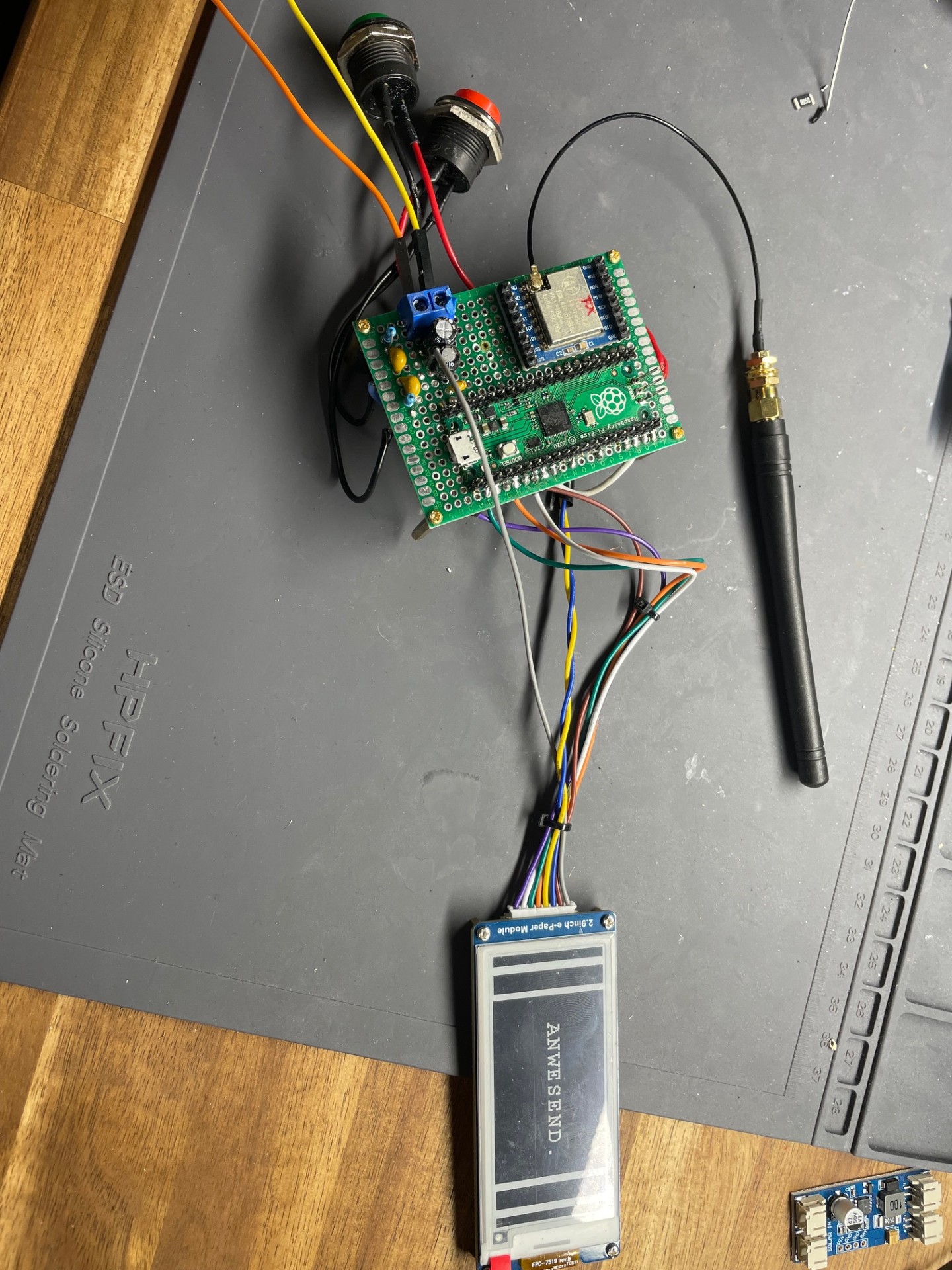
First thing I wanted to do, was to have a look at the high frequency signal induced by my chair, that appeared to interfere with the GPIO Interrupts in such way that the RP2040 woke up from DORMANT mode. Figure 1 shows the breadboard of the sender device. Now that I use low pass filters (where the yellow capacitors are, on the bottom of the board) and shorter cables, the problem doesn´t appear anymore. It was just nice to see the impact of EMI on my own project, where I´d least expected it.
By successfully putting the sender in DORMANT mode and receiver into SLEEP mode, I made sure that the devices save power, when they are not communicating, since I want to power them off of a simple rechargable Battery (e.g. 3.7 V Li-Ion).
Although that was the biggest step to make this application "Low Power", there is still the problem that the indicators for the presence (LED´s) draw a current of around 5-7 mA. I don´t think that this would be low power, since a simple device like that should power for months, like these digital scales or remote controls.
For that reason I was thinking about E-Ink displays, which are made out of an array of colored particles. These displays only draw a current when they switch to a new image. After that, they can go into sleep mode and draw 0 mA (ideally). Even when you unplug the display the last image stays on, making it a perfect fit for this project.
However, since I eventually want to put the device in a housing, I have soldered the LoRa device and the RP2040 with its connections and terminal blocks on breadboards to have just one board for the sender and one for the receiver (figure 1). I don´t know where I will place the electronics for the solar panel and the battery yet, but we leave that for later.
Connections
The 2.9inch Waveshare E-INK Display V.2 is a SPI Device, so I soldered the MISO/MOSI - Pins to the SPI bus which the LoRa device already uses. All connections are shown in the table below.
| E-Ink | RP2040 Pin |
|---|---|
| VCC | 5V |
| GND | GND |
| DIN (SPI MOSI) | GP19 |
| SCLK(SPI SCK) | GP18 |
| CS (SPI chip selection) | GP5 |
| DC (Data / Command selection - high for data, low for command) | GP2 |
| RST (External reset, low active) | GP6 |
| BUSY (Busy status output - high for busy) | GP1 |
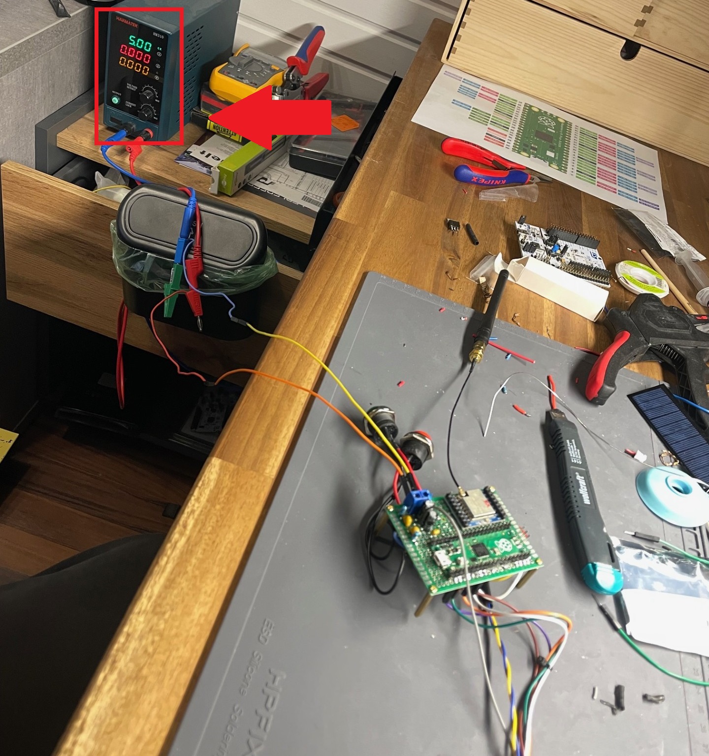
Leakage Current or "NOSLEEP" Current
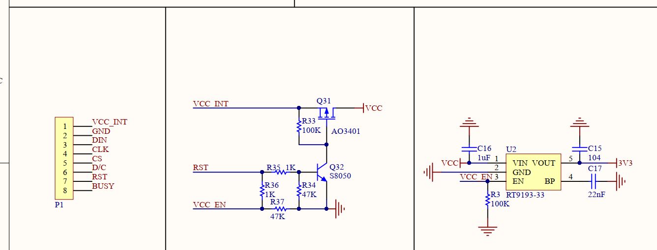
When I bought the E-Ink display, I was thinking that it won´t draw any current when it is not used, by using an on-board switch or an internal SLEEP mode. Although there is a SLEEP mode, which I use, the display still drew a current of around 4-7 mA. While measuring through the pins of the display, I recognized a voltage of 3.3V on the RST pin, even without the VCC connected. Since I use the official library of the waveshare 2.9 inch V2, and have changed some things in it anyways to make it fit to my project, I saw that the Sleep() doesn´t put the RST pin LOW while going to sleep. The official schematic shows that keeping it HIGH would keep the internal VCC active (see Figure 2). They even have a NMOS/PMOS load switch for that.
      //epd2in9_V2.cpp

      void Epd::Sleep() {
        SendCommand(0x10);
        SendData(0x01);
    }
Therefore I have changed the function a little to set RST LOW while going to sleep.
      //CHANGED epd2in9_V2.cpp

      void Epd::Sleep() {
        SendCommand(0x10);
        SendData(0x01);
        //added because if RST pin high then pwr doesn´t turn off
        DelayMs(10);
        DigitalWrite(reset_pin, LOW);
    }
After this adjustment it didn´t draw any more uneccesary currents in SLEEP mode.
Library and Code
Official Github Repository of Waveshare 2.9in V2 E-INK DisplaySince in the last section we have already started by changing the code, we will go on with the programming in such way that, on the sender device, the display changes on a pressed button, while the receiver does the same but on a received signal. Essentially we only swap the previous code that put the LED´s in their states with the code to write something on the display.
To be able to use the correct firmware we need to visit the Github link above. After that we need to go back to the e-Paper folder, download it and extract Arduino/epd2in9_V2 for the black and white 2.9inch V2 display. I placed the folder in Arduino/libraries.
You can open the .ino file in the folder to see how it works and experiment with it. To start with, you can try and import the following lines and compile. If it works then you are ready to go:
#include "epd2in9_V2.h"
#include "epdpaint.h"
Attention with the RAM Storage
Since the code is written for Arduino UNO, there is the note that the RAM is too small (2kB) and the display (296*128/8 = 4736 Bytes) needs to be updated partially.
/**
* Due to RAM not enough in Arduino UNO, a frame buffer is not allowed.
* In this case, a smaller image buffer is allocated and you have to
* update a partial display several times.
* 1 byte = 8 pixels, therefore you have to set 8*N pixels at a time.
*/
unsigned char image[1024];
Paint paint(image, 0, 0);    // width should be the multiple of 8
Epd epd;
However since I use the RP2040 I have 192 kB to use which is more than enough, so I was able to define the image with the full size of 4736 Bytes and update the image as a whole instead of partially.
//Has to be like this on pi pico because if 1024 used
//like in example heap errors/overflows occur

unsigned char image[296 * 128 / 8];
Paint paint(image, 0, 0);
Epd epd;
Changes in the firmware
In the epdif.h file of the downloaded lib are the definitions for the used pins. I have changed the pins, because some of them are already in use or too close to other connections.
#define RST_PIN         6
#define DC_PIN          2
#define CS_PIN          5
#define BUSY_PIN        1
Furthermore there was a PWR_PIN defined. It gets set HIGH in the
int EpdIf::IfInit(void). Since it didn´t make sense to
me, I commented out that definition and the 2 lines of code.
Implementation "Present" and Abscence
Now we can implement the functions in the main program. I have two
functions for that showPresenceOnDisplay() and
showAbscenceOnDisplay()
#define COLORED     0
#define UNCOLORED   1

void showPresenceOnDisplay(){


  epd.Init();
  epd.Reset();
  delay(10);

  epd.ClearFrameMemory(0xFF);   // bit set = white, bit reset = black
  epd.DisplayFrame();

  paint.SetRotate(ROTATE_90);
  paint.SetWidth(128); //128 Width ist die höhe wenn horizontal gehalten
  paint.SetHeight(200);//296


  paint.Clear(UNCOLORED);
  paint.DrawFilledRectangle(0,0,10,128,COLORED);
  epd.SetFrameMemory(paint.GetImage(), 0, 0, paint.GetWidth(), paint.GetHeight());

  paint.Clear(UNCOLORED);
  paint.DrawFilledRectangle(0,0,20,128,COLORED);
  epd.SetFrameMemory(paint.GetImage(), 0, 20, paint.GetWidth(), paint.GetHeight());


  paint.Clear(COLORED);
  paint.DrawStringAt(30, 50, "ANWESEND.", &Font24, UNCOLORED);
  epd.SetFrameMemory(paint.GetImage(), 0, 48, paint.GetWidth(), paint.GetHeight());


  paint.Clear(UNCOLORED);
  paint.DrawFilledRectangle(0,0,20,128,COLORED);
  epd.SetFrameMemory(paint.GetImage(), 0, 256, paint.GetWidth(), paint.GetHeight());


  paint.Clear(UNCOLORED);
  paint.DrawFilledRectangle(0,0,10,128,COLORED);
  epd.SetFrameMemory(paint.GetImage(), 0,286, paint.GetWidth(), paint.GetHeight());


  epd.DisplayFrame();

  epd.Sleep();
}

void showAbscenceOnDisplay(){

  epd.Init();
  epd.Reset();
  delay(10);


  epd.ClearFrameMemory(0xFF);   // bit set = white, bit reset = black
  epd.DisplayFrame();

  paint.SetRotate(ROTATE_90);
  paint.SetWidth(128); //128 Width ist die höhe wenn horizontal gehalten
  paint.SetHeight(200);//296

  // For simplicity, the arguments are explicit numerical coordinates
  paint.Clear(COLORED);

  paint.DrawStringAt(15, 40, "Bin gerade", &Font24, UNCOLORED);
  paint.DrawStringAt(15, 70, "nicht da.", &Font24, UNCOLORED);
  epd.SetFrameMemory(paint.GetImage(), 0, 0, paint.GetWidth(), paint.GetHeight());

  paint.Clear(UNCOLORED); //Hier passiert das problem
  paint.DrawFilledRectangle(0,0,20,128,COLORED);
  epd.SetFrameMemory(paint.GetImage(), 0, 210, paint.GetWidth(), paint.GetHeight()); //Offset y = 210 x=0 absolute

  paint.Clear(UNCOLORED);
  paint.DrawFilledRectangle(0,0,15,128,COLORED);
  epd.SetFrameMemory(paint.GetImage(), 0, 240, paint.GetWidth(), paint.GetHeight());

  paint.Clear(UNCOLORED);
  paint.DrawFilledRectangle(0,0,10,128,COLORED);
  epd.SetFrameMemory(paint.GetImage(), 0, 265, paint.GetWidth(), paint.GetHeight());

  paint.Clear(UNCOLORED);
  paint.DrawFilledRectangle(0,0,5,128,COLORED);
  epd.SetFrameMemory(paint.GetImage(), 0, 285, paint.GetWidth(), paint.GetHeight());

  epd.DisplayFrame();


  epd.Sleep();
}
The first thing to do after wakeup is to epd.Init() and the
last thing to do after updating the display is
epd.Sleep() The rest is just coloring and updating the frame.
there are many examples in the .ino file. You can try them out.
Now remember the code from the last time ? Instead of the LED´s I set the display functions, after getting a response from the receiver:
// ------------------------------------------------------------------------------------------------------- //
// ------------------------------ wait for response of the receiver -------------------------------------- //
// ------------------------------------------------------------------------------------------------------- //

if(messageSent){
  messageSent = false;

  // wait for response for 1.5 seconds
  unsigned long startTime = millis();
  while(millis() - startTime < 1500){


    int packetSize = LoRa.parsePacket();
    if (packetSize) {

      //read received string
      while (LoRa.available()) {
        String received = LoRa.readString();

        uint8_t* receivedBytes = stringToBytes(received);
        aes.decryptBlock(decryptedResponse,receivedBytes);

        if(checkReceivedTextCorrect(decryptedResponse,(char*)sendTextOn)) {

          showPresenceOnDisplay();
          currentState = true; //means that display state is now "present"

        }
        else if(checkReceivedTextCorrect(decryptedResponse,(char*)sendTextOff)) {

          showAbscenceOnDisplay();

          currentState = false; //means that display state is now "not present"
        }

      }
    }
    delay(80);
  } //while end
}
The changes in the receiver code are similar:
  if (packetSize) {
    noPacketCounter = 0;


    // Read and display received data
    while (LoRa.available()) {

      String received = LoRa.readString();

      uint8_t* receivedBytes = stringToBytes(received);

      //Decrypt
      aes.decryptBlock(decrypted,receivedBytes);


      if(checkReceivedTextCorrect(decrypted,(char*)sendTextOn)) {


        //Success send response
        sendResponse(sendTextOn);
        showPresenceOnDisplay();

      }
      else if(checkReceivedTextCorrect(decrypted,(char*)sendTextOff)) {

        //Success send response
        sendResponse(sendTextOff);
        showAbscenceOnDisplay();
      }


    } //while end
Results
By using the E-Ink display I managed to make this device low power, which only draws a "siginificant" amount of current when it´s used after pressing a button.
I have already prepared a Li-Ion Battery Cell with around 2850 mAh for each device. If we say that it approximately(not calculated) draws constantly 1mA (SLEEP and Active phase combined), it would last
2850 mAh / 1 mA = 2850 h = 118.75 d = 3.95 months
Since "the user" cannot replace the batteries, I am thinking of using a small solar panel, that trickle charges the battery. To make it last way longer. However that will be the next part of my project... ¯\_( ͡❛ ͜ʖ ͡❛)_/¯